Overview
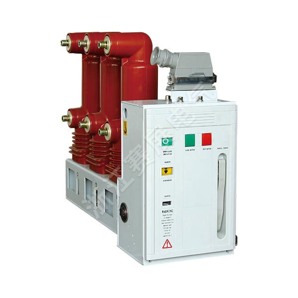
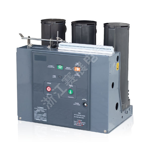
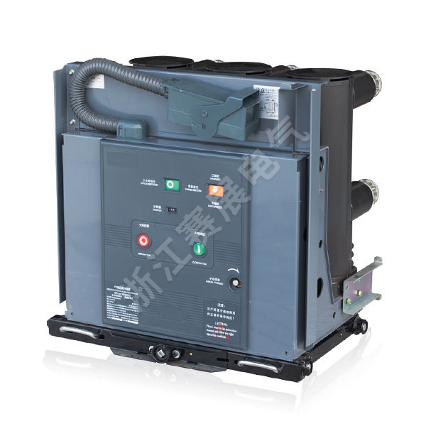
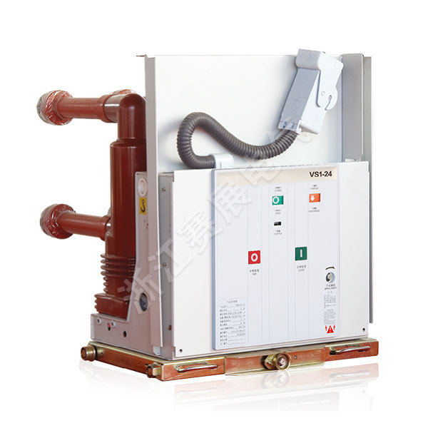
VSC-12 indoor high-voltage vacuum circuit breaker (hereinafter referred to as circuit breaker) is suitable for indoor switchgear of 12kV power system. As a protection and control unit for power grid equipment and power design of industrial and mining enterprises, it is suitable for switching various Loads and frequent operations, breaking short-circuit current many times. The product adopts a new circuit breaker operating mechanism, and the primary part of NGVSC can use international brand solid-sealed poles to seal the vacuum interrupter and the main conductive circuit parts into a whole to protect the interrupter from collision, dust and condensation. It has strong environmental adaptability, greatly reduces operation and maintenance costs, and truly realizes the one-time part maintenance-free product and less maintenance of the operating mechanism; the operating mechanism and the circuit breaker body are designed in one piece, which has been verified by type tests; it has E2-level electrical life. , M12 mechanical life.
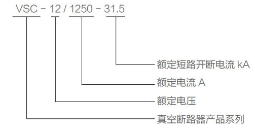
产品型号及含义
Product structure and working principle
■Main structure
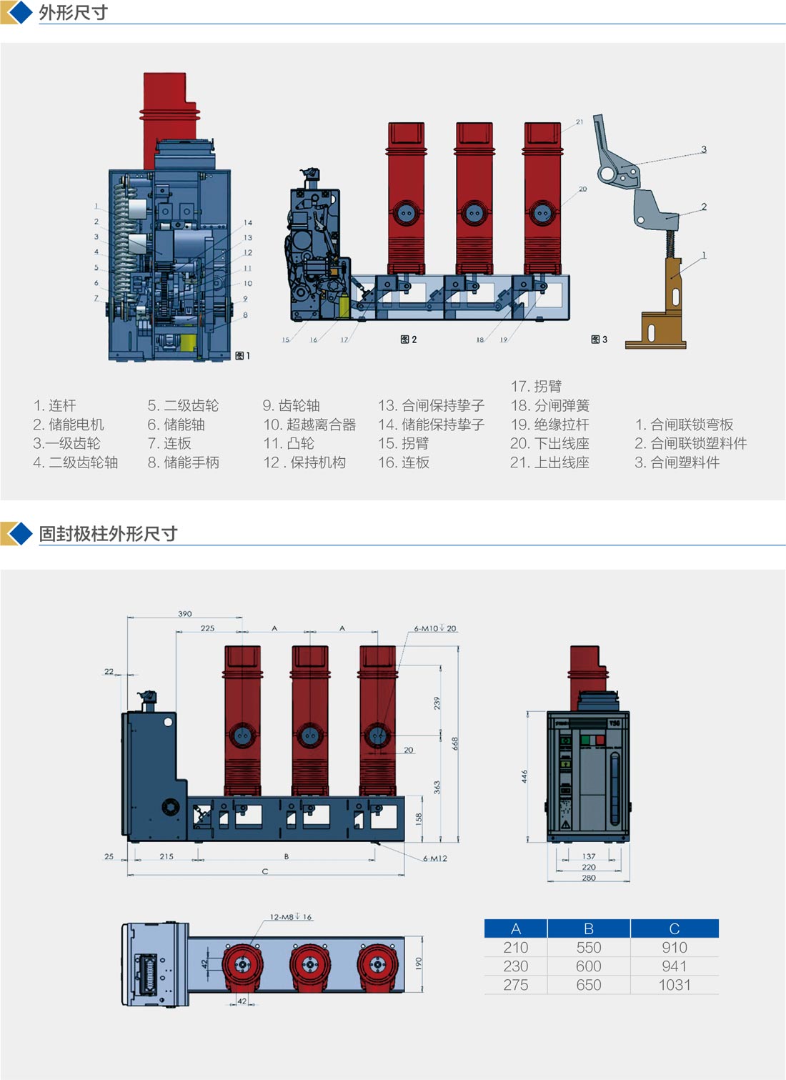
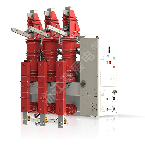
The overall structure of the VSC indoor high-voltage vacuum circuit breaker adopts the form of an operating mechanism and a front and rear arrangement of the primary part, and the primary part is a three-phase floor-standing structure. The upper and lower outlet sockets and the arc-extinguishing chamber are integrally sealed by epoxy resin APG process, so that there is no dust accumulation on the surface of the arc-extinguishing chamber, which can prevent the vacuum arc-extinguishing chamber from being damaged by external factors, and ensure that it can be used in hot and humid and dirty environments. in more severe circumstances.
The main circuit current path when the circuit breaker is in the closed position: (see Figure 2)
The upper outlet socket 21 is connected to the internal static contact of the vacuum interrupter, and then reaches the lower outlet socket 20 through the movable contact, the movable conductive rod and the soft connection connected with it.
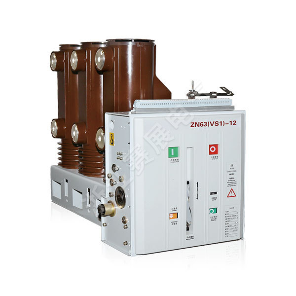
■Operating mechanism (see Figure 1, Figure 2)
The operating mechanism is a modular spring energy storage operating mechanism. The operating mechanism is integrated with a closing unit, an opening unit composed of one or more overcurrent trip electromagnets, auxiliary switches, indicating devices and other components; the front is equipped with closing, Split button, manual charging handle, spring charging status indicator, combined and split indicator, etc.
■Energy storage
The energy required for closing the circuit breaker is provided by the energy stored in the closing spring. The energy storage can be done either by an external power supply to drive the motor or manually using the energy storage handle.
Energy storage operation: carried out by the energy storage motor 2 fixed on the side plate of the mechanism, or by pulling the energy storage handle 8. The gear transmission system (3, 4, 5) is driven by the motor during electric energy storage, and the gear 5 is driven by the gear shaft 9 during manual energy storage. When the gear 5 rotates, the overrunning clutch 10 makes the energy storage shaft 6 follow the rotation to stretch the closing spring to charge the energy. When the energy storage position is reached, the energy storage detent 14 on the mechanism bears against the roller on the cam, and the overrunning clutch is disengaged. At the same time, the connecting plate 7 drives the energy storage indicator to turn over to display the "charged" mark and switch the auxiliary switch to cut off. The energy storage motor power supply, at this time, the circuit breaker is in the ready state of closing.
■Close
During the closing operation, no matter if the "close" button is pressed by hand or the closing electromagnet is actuated by remote operation, the energy storage holding detent 14 can be rotated, so that the detent releases the roller on the cam 11 and closes the The brake spring shrinks and drives the cam 11 to rotate through the energy storage shaft 6 and the overrunning clutch, and the cam drives the link mechanism (15, 16, 17) to drive the insulating rod 19 and the movable contact into the closing position, and compress the contact disc spring, The contact pressure required to maintain the contacts. After the closing action is completed, the closing holding detent 13 and the rollers on the holding mechanism 12 maintain the closing position, at the same time, the energy storage indicator and the energy storage auxiliary switch are reset, and the motor power supply circuit is connected. If the external power supply is also turned on, it will enter the energy storage state again, the connecting rod 1 pulls the closing/opening indicator, and the "close" mark is displayed, and the transmission link pulls the main auxiliary switch to switch.
■Open
You can press the "open" button, and also reliably connect the external power supply to make the opening tripping electromagnet or the overcurrent tripping electromagnet act to unlock the closing holding detent 13 and the roller on the holding mechanism 12 to realize the opening. operate. The energy stored by the contact spring and the opening spring 18 separates the static and dynamic contacts of the arc-extinguishing chamber in the solid-sealed pole. In the latter part of the opening process, the hydraulic buffer absorbs the remaining energy of the opening process and defines the separation position.
Pull the closing/dividing sign by connecting rod 1 to display the "min" mark, and pull the counter at the same time to realize the counting of the counter, and the main auxiliary switch is pulled by the transmission link to switch.
Note: When the circuit breaker is already in the closed state or the locking device is selected without unlocking the locking device, and the handcart-type circuit breaker is in the process of pushing out, the closing operation cannot be performed.
■Anti-mistake interlock
The circuit breaker can provide perfect anti-misoperation function. (See Figure 3, Figure 4)
1. After the closing operation of the circuit breaker is completed, the closing interlock bending plate
1 Move up to make the closing interlocking plastic part 2 fasten the closing plastic part 3 on the closing holding shaft, and the circuit breaker cannot be closed again when the circuit breaker is not opened.
⒉. After the circuit breaker is closed, if the closing electrical signal is not removed in time, the internal anti-jump control circuit of the circuit breaker will cut off the closing circuit to prevent multiple reclosing.
3. If electrical closing lockout is selected, the closing operation is prevented without unlocking the lockout device.
Note: The power of the closing blocking device is 3.2W, and the working voltage range is 0.65~1.1 times the rated voltage.